![]()
![]()
![]()
Use LEFT and RIGHT arrow keys to navigate between flashcards;
Use UP and DOWN arrow keys to flip the card;
H to show hint;
A reads text to speech;
122 Cards in this Set
- Front
- Back
- 3rd side (hint)
|
(VPN) VIRTUAL PRIVATE NETWORK
|
private network that extends over a public network.
|
private secure neighborhood within a public city. these neighborhoods are accessed by secure encrypted roads that run through and across public city's domains
|
|
|
web servers
|
process and delivers webpages to clients using the http protocols.
|
public or private information storehouse thats handles http webpage request from clients
|
|
|
SWITCHING METHODS
(STORE & FORWARD ) |
switch receive all bits of frame before forwarding it. the switch checks the frame for errors.
|
more secure method of switching.
|
|
|
when choosing routing protocols consider these factors
|
proprietary. vs. open protocols, scalability, routed protocol support, ease of administration, and speed of convergence.
|
|
|
|
CLASS A IP ADDRESS |
* public network ID range (1-126 ) * private network ID range (10.0.0.0 - 10.255.255.255 ) * usually reserved for large corporations * ( network.node.node.node ) * 16 million host devices * 127 seperate subnetworks * subnet mask = 255.0.0.0 * CIDR = /24 |
|
|
|
CLASS B ADDRESS |
public ip range 128 - 191 private ip range 172.16.0.0 - 172.31.255.255 subnet mask 255.255.0.0 16,384 potential networks 65,534 potential host (network.network.node.node) |
g |
|
|
CLASS C ADDRESSES |
public ip range 192 - 223 private ip range 192.168.0.0 - 192.168.255.255 subnet 255.255.255.0 254 potential host 2 million potential networks ( network.network.network.node) |
g |
|
|
ROM |
contains micro-code for basic functions to start and maintain router. |
g |
|
|
RAM/DRAM |
stores running config, routing tables and packet buffers. |
|
|
|
NVRAM |
stores system configuration register, & other config files. |
|
|
|
FLASH MEMORY |
stores compressed IOS image |
|
|
|
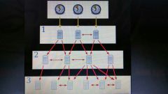
Router Boot Sequence |
1.NVRAM 2. FLASH MEMORY 3. TFTP SERVER 4. ROM |
|
|
|
Important Port Numbers |
port 20-21 (FTP) port 23 (telnet) port 25 (smtp) port 53 (dns) port 67-68 (dhcp) port 69 (tftp) port 80 (http) port 110 (pop3)
|
|
|
|
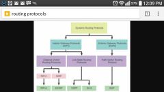
DISTANCE VECTOR PROTOCOLS |
-determine direction & distance - uses hop count - smaller the metric the better the path - (ex) RIP & IGRP - very little overhead - based on bellma & ford algorithms - they dont support ( VLSM & CIDR ) |
|
|
|
LINK STATE PROTOCOLS |
- use SPF & Dijkstra algorithims - very scalable supports infinite hops - the metrics are bandwidth & delay - generate exact topology of network - (ex) OSPF & NLSP - require more router CPU and memory - dont advertise full routing table. |
|
|
|
Hybrid |
(ex) EIGRP uses aspects of both distance vector & link state protocols |
|
|
|
classful routing protocols |
- do not exchange subnet information - summerization is automatic |
|
|
|
classless routing protocols |
- subnet info is exchanged during routing updates - summerization is manually |
|
|
|
Administrative Distances |
static route = 1 internal EIGRP = 90 IGRP = 100 OSPF = 110 RIP = 120 IS IS = 115 External BGP = 20 Internal BGP = 200 |
|
|
|
static NAT |
maps private ip addresses to public ip addresses on a 1 to 1 basis. |
|
|
|
dynamic NAT |
maps a group of private ip addresses to a pool of public ip addresses |
|
|
|
NAT Overloading (aka) Port Address Translation |
- maps multiple private ip's to one single public ip. - uses port information from the transport layer to dynamically create a NAT table - (aka) Port Multiplexing |
|
|
|
Setting Router Passwords |
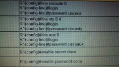
console line vty lines auxiliary port enable secret encrypted enable password unencrypted |
|
|
|
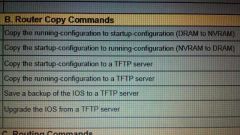
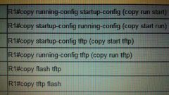
ROUTER COPY COMMANDS |
|
|
|
|
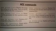
show access-list |
displays access list from all protocols |
|
|
|
crossover cable |
used to connect two similar devices or systems. or router to pc |

|
|
|
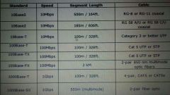
ETHERNET STANDARDS |
|

|
|
|
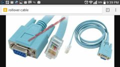
rollover cable (aka) console cable |
connects to serial port and is for config purposes |
|
|
|
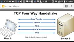
TCP Three-way handshake |
SYN, ACK/SYN, ACK |
|
|
|
ROUTING PROTOCOLS |
- exchange network routes and metric information - help build routing tables - do not route data packets |
|
|
|
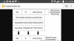
ROUTED PROTOCOLS |
- tag each data packet with source and destination addresses - assign a unique logical addresses to each node on network - they do route data packets |
|
|
|
Ethernet Technical Considerations |
1. topology 2. bandwidth 3. transmission mode 4. cabling 5. maximum range |
|
|
|
NVRAM |
- holds startup config files - doesnt lose info when power is lost - stores system config files - stores config registar - has small battery |
|
|
|
Rollover cable |
use to connect to console interface |
|
|
|
SERVICE PROVIDER (isp) |
telecom companies that provide shared bandwidth or dedicated connections over a their WANs |
|
|
|
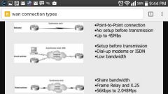
Types of WAN Connections |
1.dedicated lease line 2. circuit switched 3. packet switched 4. cell switched |
|
|
|
Dedicated Leased Lines Connections |
data communication link used exclusively by one customer.
advantages = alot of bandwidth, privacy, reliability & customize.
disadvantages = cost,multiple PPP links. |
these connections used HDLC,PPP and SLIP |
|
|
Circuit Switched Connections |
use telephone communication infrastructure to send and receive data. advantage = availiability disadvantage = low speeds,high cost |
this connection uses HDLC,PPP & SLIP |
|
|
Packet switched connections |
users connect to a ISPs network and share bandwidth advantage = cheap ,fast, reliabile, easy setup disadvantage = possible traffic spikes,limited customize,security risks |
this connection uses x.25 and frame relay |
|
|
Cell Switched Connection |
work the same as packet switched connections except for all frames are the same size, so there processed faster , best suited for voice and video connections
advantage = speed disadvantage = overhead, wasted bandwidth |
this connections use ATM Protocols |
|
|
wireless AD HOC Mode |
two or more wireless devices connected to each other. no Access points required. peer2 peer setup that uses automatic private IP Addresses. |
potentially subject to man in the middle attacks. |
|
|
wireless Infrastructure mode |
- uses build in networking infrastructure to form a wireless network, (switches, routers ,firewalls, access points & wireless LAN controller services) - opposite of AD HOC networks, |
|
|
|
radio frequency factors |
absorption, reflection, scattering |
|
|
|
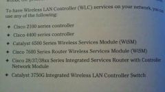
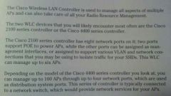
cisco wireless LAN controllers |
g |
|
|
|
cisco 2100 & 4400 wireless LAN controllers |
|
|
|
|
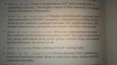
NAT inside local address |
internal private address of host |
|
|
|
NAT inside global address |
- addresses issued by your ISP - public internal address that is linked to your private internal address. |
|
|
|
troubleshooting NAT |
1. review the configuration 2. review NAT translation table 3. use CLI commands (show & debug)commands 4. analyze the path of the packet. |
|
|
|
Access Control List COMMANDS |
|
|
|
|
Standard access list |
- list range 1-99 & 1300-1999 - use to filter traffic based on ip source addresses. - apply on interfaces near the destination. |
|
|
|
extended access control list |
- list range 100-199 & 2000-2699 - filters based on source address, destination address, type of protocol, port number, hop count |
|
|
|
EIGRP |
- deleveloped by cisco - tracks its neighbors - uses bandwidth & delay to calculate the quality of a route. - summerizes routes by default - can leverage routes found by other routing protocols - EIGRP can also route packets for IP, IPX, & APPLETALK. - to configure EIGRP ( startup eigrp on all network routers, enable eigrp on all nessicary router interfaces, config optional protocol parameters
|
|
|
|
PPP (point to point protocol) |
- features of PPP include multilink bonding, callback and authentication security. - the sublayer protocol LCP sets up the PPP link, negiotiates authentication options, uses maintence, termination, configuration frames. - the sublayer protocol NCP. is responsible for layer 3 traffic over the link - (optional phases) network link protocol, link quality determination - PAP unsafe protocol. - CHAP handshake process consost of (challenge,response & verification) |
|
|
|
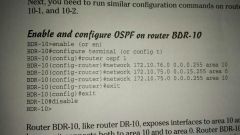
Characteristics of OSPF |
- route updates are sent only when changes occurs - is supported by non Cisco routers - supports VLSM - supports unlimited network hops - divides autonomous systems into areas - converges quickly - LSA packets have small footprints - LSA traffic is minimized when routes are summarized |
|
|
|
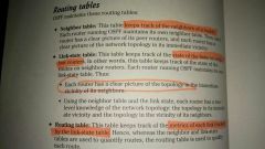
OSPF " 3 routing tables " |
1. neighbor table = tracks and maintains OSPF neighbors 2. Link state table = monitors the health of all neighboring links 3. Routing table = tracks the metrics of each link |
|
|
|
The 5 OSPF Link state advertisements (LSA) |
1. Router LSA = describes the status of the routers links. Generated by all routers in the area. 2. Network LSA = generated by the D.R in multi-access network. Describes a set of routers attached to a particular network. 3. |
|
|
|
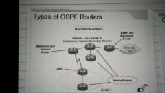
OSPF router types |
Internal routers = all interfaces inside same area Area border routers = one interface in each of the two areas Backbone area = at least one interface resides in area 0 AS border router = one interface resides in a non-ospf area. |
|
|
|
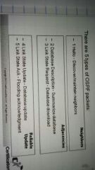
5 OSPF packet types |
1.Hello = discover maintain neighbor's 2.Database description = summarize database 3. Link state request = database download 4. Link state update = database update 5. Link state Ack = flooding acknowledgement |
|
|
|
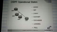
Ospf operational States |
2. Init - hey hello packet has been seen 3. 2-way - neighborship has been established (election for Dr/bDr may now occur) 1. Down - no recent information received number2. Init - hey hello packet has been seen3. 2-way - neighborship has been established (election for Dr/bDr may now occur)4. Exstart - first phase of adjacency established. Dr/bDr asserts authority. 5. Exchange - Dr sends dbd's to client, may request LSA from client6. Loading - Dr ask for a most recent LSA's7. Full - link State databases are synchronized 4. Exstart - first phase of adjacency established. Dr/bDr asserts authority. 5. Exchange - Dr sends dbd's to client, may request LSA from client 6. Loading - Dr ask for a most recent LSA's 7. Full - link State databases are synchronized |
|
|
|
OSPF's ( 3 routing tables ) |
Neighbor table - keeps track of its neighbors and has a clear picture of the network topology Link State table - keeps track of the state of the links/routes on neighbor routers Routing table - tracks the metrics of all links on neighboring routers |
|
|
|
OSPF ( designated router ) |
- is responsible for keeping all routers in the ospf updated on the shortest path - ospf routers only exchange route information with the Dr router. - the Dr router then updates everyone on the new route available |
|
|
|
OSPF ( designated router ) 2 |
winning the Dr election process.
1. Create loopback interfaces on each router in your network set the highest IP address on the router you want to elect the Dr 2. Set the highest OSPF priority on the router and interface you want to elect as the Dr |
|
|
|
Troubleshooting frame relay Networks |
1. Verify physical connection between the router and CSU/DSU 2. Verify LMi exchange between the DTE and DCE 3. Verify the state of the virtual circuit is set to active 4. Verify encapsulation types are identical between routers |
|
|
|
Frame relay virtual circuits |
- virtual circuits must travel across multiple DCE's to connect two DTE's devices together
- there are two kinds of virtual circuits (PVC) permanent virtual circuit & (SVC) switched virtual circuit - multiple virtual circuits can be active on the same DTE interface by using subinterfaces |
|
|
|
Permanent virtual circuit frame relay (PVC) |
- permanent connection, always on, never terminated
- (pvc's have two functions) 1. Data transfer = data traffic flows between DTE's using a PVC as the transport mechanism
2. Idle = connection between DTE s is up but there is no data flowing on the link |
|
|
|
Switched virtual circuits frame relay. (SVC) |
- connections maintained on temporary basis cheaper then PVC - ( SVC has four functions ) 1. Call setup - a logical circuit is created between customers DTE's 2. Data transfer - data is sent between DTE's 3. Idle - no data is being sent 4. Call termination - the virtual circuit is shut down |
|
|
|
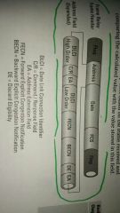
(DLCI) data link connection ID |
- Unique number assigned by the ISP to identify individual links. - this number refers to a logical path through the frame relay Network - each segment of the virtual circuit maybe assigned a different DLCI value - virtual circuits insert the DLCI value into the frame relay frame header - DLCI is the main factor in determining data delivery decisions - DLCI is the frame relay equivalent of a MAC address |
|
|
|
Access rate frame relay |
- The maximum data transfer speed between two DCE - the access rate is defined on a per Port basis - the data transfer speed sets the clocks speed |
|
|
|
(CIR) committed information rate |
- maximum bandwidth size guaranteed by ISP for data transmission over the wan link. (this value is measured overtime and fluctuates ) |
|
|
|
Local management interface (LMI) Frame relay |
- signaling control protocol between the customers DTE and the ISP's DCE, it monitors and manages the status of the link and its devices (3 types of LMI) 1.Cisco - LMI type set by default on all Cisco routers 2. ANSI - LMI specification defines signaling process 3. Q933a - access signaling specification define by the ITU
- both the DTE and the DCE must use the same type of LMI - Cisco routers can auto sense the LMI type - LMI also listen for other LMI traffic |
|
|
|
OSPF ( backup designated router ) |
- the backup designated router also sees the same LSA's as designated router - routers send their packets to a multicast address 224.0.0.6 & 224.0.0.5 - the Dr & BDr both listen to multicast address 224.0.0.6 & 224.0.0.5 |
|
|
|
How to inspect the routing table |
Show IP route command |
|
|
|
How to inspect OSPF protocol configuration |
Show IP protocols command |
|
|
|
How to inspect the OSPF interface configuration |
Show IP OSPF interface command |
|
|
|
How to inspect the OSPF neighbor information |
Show IP OSPF neighbor command |
|
|
|
How to inspect ospf routing database |
Show IP OSPF database command |
|
|
|
Characteristics of OSPF |
- route updates (LSA) only occur when our network change has occurred - routers exchange hello messages during the convergence process to build their neighbor tables - OSPF support VLSM, non-cisco routers, unlimited hot counts, |
|
|
|
OSPF ( basic configuration ) |
Don't forget the loopback interfaces |
|
|
|
frame Relay ( congestion control fields ) |
these are three one bit congestion control and fields known as FECN, BECN & DE. congestion control bits trigger upper layer protocols to mitigate congestion using flow control whenever the Wan link becomes overloaded |
|
|
|
Inverse ARP Frame Relay |
- inverse ARP was developed for frame relay networks to reduce traffic congestion during address resolution ( enable by default) - dynamically maps protocol addresses (layer 3) to a DLCI address (layer 2) after of virtual circuit is established - sent every 60 seconds - dynamic address mapping is automatic if LMI and inverse ARP are available - frame relay mapping can be statistically introduced by the administrator by using the (frame relay map command) |
|
|
|
Frame relay topology (Star topology) |
- most popular frame relay method - uses least amount of PVC's - simplifies management and reduces operational cost - most efficient for connecting multiple Virtual circuits - one hub device acts as a central communication point - the central router is a single point of failure on which the entire network depends - limited performance |
|
|
|
(BPDU) Bridge protocol data unit |
- data packets that is sent at defined intervals for the purpose of exchanging information with switches in the network. - all bpdu's are sent to a multicast address 01-80-c2-00-00-00 - there are two types of bpdu's ( topology and configuration) - set out every 2 seconds
|
|
|
|
Bridge ID |
- used to find and elect the root bridge in a STP environment - Bridge ID is a combination of the bridge priority and MAC address address |
|
|
|
Designated bridge |
Hg |
|
|
|
Designated Port (STP) |
- the only Port that can communicate with the route bridge - only one per Network - the (DP) is the root port with the lowest root Port cost |
|
|
|
Root bridge (STP) |
- the switch with the lowest bridge ID |
|
|
|
Spanning tree protocol |
Hfg |
|
|
|
Spanning tree algorithm |
- computers redundant paths from one common point to each switch on the network. - the shortest (least costly) path is designated the active path - the remaining paths are placed on blocking list - this prevent loops in the network |
|
|
|
Root Bridge election process |
1. when are switch powers up it advertises its bpdu which contains it's bridge ID. 2. All switches then compare there bpdu's to each other's. 3. The switch with the lowest bridge ID wins |
|
|
|
The 5 states of Spanning tree protocol |
1. Disabled 2. Blocking 3. Listening 4. Learning 5. Forwarding |
|
|
|
STP timers |
1. The Hello timer - the amount of time that expires between the exchange of bpdu's 2. The forward delay timer - the time Interval between the ports listening and forwarding State 3. The maximum age timer - the life span of a bpdu |
|
|
|
Portfast (STP's) |
- allows a port to override the Forwarding delay timer thus allowing it to move from a listening State to a forwarding State instantaneously |
|
|
|
Uplinkfast (STP) |
A backup Port that is in the blocking State will begin forwarding frames ass soon as it detects the primary interface(root port) has gone offline |
|
|
|
Backbone fast (STP) |
- allows a root Port or root bridge to detect and compensate for a link failure somewhere in the network |
|
|
|
Verifying spanning tree protocol |
- show spantree command |
|
|
|
STP decision criteria |
- lowest root bridge ID - lowest root path cost to root bridge - lowest sender bridge ID - lowest port ID |
|
|
|
Root port (STP) |
- Port most directly connected to the root bridge |
|
|
|
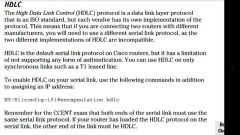
HDLC ( high level data link control protocol) |
- layer 2 protocol - connects point to point lease lines - has error correction - Only works on Cisco devices - default encapsulation on serial interface |
|
|
|
Network time protocol (NTP) |
Makes sure all cisco devices on the network have the same time and date.
Multiple services and protocols depend on all the network devices being in sync with correct time and date
NTP works best if you manually set the current devices time, date, time zone and daylight saving first.
If there are multiple NTP servers, routers will choose the one with the lowest stratum number Sometimes the NTP server's physical interface ip address goes down. Use a loopback ip address as a backup route just in case.
NTP.pool.org |
|
|
|
NTP configurations |
(Clock timezone est-5 ) = sets timezone
(Clock summer-time edt recurring) = sets daylights savings
(Ntp server x.x.x.x) = configs the client device to sync with the ntp server
(Ntp server x.x.x.x prefer) = configs one device to be the lead in a peer group of multiple ntp server's
(Ntp peer x.x.x.x) = configs a group of NTP servers, the server with the lowest stratum becomes the group lead.
(Ntp master (stratum #) = configs a cisco device as a ntp server.
(Show ntp associations) = shows ntp peers and other related information
(Show ntp status) = shows clock synchronization
(Show clock) = shows current time and date on cisco device's |
|
|
|
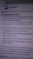
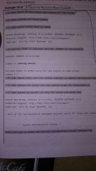
Syslog ( system messaging logging ) |
When the cisco IOS notices an event it tries to notify someone.
Anyone logged in through the console port will automatically see these Syslog messages
|
|
|
|
(Syslog) Storing log messages for later |
(Logging monitor) - tell the ios to enable log messages to all logged in users
(Terminal monitor) - tells the ios that this terminal session wants to receive log messages
(Logging buffered) - stores copies of log messages on Ram
( logging trap #) - sets the log message level for the syslog server (Show logging) - list log configurations & old messages
(Clear logging) - erases old log messages from Ram
( logging x.x.x.x or hostname) - send messages to a Syslog server for storage.
( no service timestamps) - disables timestamps
(Service sequence-numbers)- enables sequence numbers in log messages |
|
|
|
Syslog ( log message Severity levels ) |
(0-1) = alert emergency (2-4) = critical event warning (5-6) = notification/informational -(7)- = debug |
|
|
|
(CDP) cisco discovery protocol |
Discovers basic information about directly connected neighboring routers & switches
CDP discovers 1. Device identifier 2. Address list 3. Port id 4.capabilities list 5. Platform Disable cdp on any interface that doesnt need cdp. |
|
|
|
(CDP) configuration |
(Show cdp neighbors) - list one summary line about each neighbor
(Show cdp neighbors detail) - shows large set of details about neighbors
(No cdp enable) - disable cdp on one particular interface (No cdp run) - disables cdp globally on the device ( show cdp) - shows cdp enabled, list default updates and hold down timers (Show cdp interface # )- shows cdp operations on the interface (Show cdp traffic) - list global statistics for cdp advertisements sent and received |
|
|
|
(LLDP) link layer discovery protocol |
Same general features as CDP Defined by IEEE 802.1ab |
|
|
|
LLDP CONFIGURATION |
(Show lldp neighbors) - (Show lldp entry # ) - (Lldp run) - (Lldp transmit & lldp receive) - ( show lldp interface) - |
|
|
|
LLDP CONFIGURATION |
(Show lldp neighbors) - (Show lldp entry # ) - (Lldp run) - (Lldp transmit & lldp receive) - ( show lldp interface) - |
|
|
|
Cisco IOS file systems on routers |
Every OS creates file systems for keeping data organized so the user or applications can find it later.
Use the (show file systems command) to see a list of all the OS file types ( show flash) - show contents of the default flash file system ( dir flash0: ) - same contents as show flash command |
|
|
|
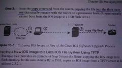
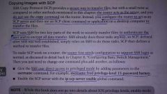
Upgrading the cisco IOS image |
1. Obtain IOS image from cisco.com by downloading the iOS image using ftp or http. 2. Place the IOS image where the router can access it. Locations include tftp server, ftp server or usb flash drive. 3. Issue the COPY command, copying the new ios image into flash memory. |
|
|
|
Upgrading the cisco IOS image |
1. Obtain IOS image from cisco.com by downloading the iOS image using ftp or http.
2. Place the IOS image where the router can access it. Locations include tftp server, ftp server or usb flash drive.
3. Issue the COPY command, copying the new ios image into flash memory. |
|
|
|
Verifying IOS code using md5 |
How to check IOS code integrity
- Cisco creates an md5 hash value for every specific iOS image file it creates. - Cisco places the code at a download site for all to see. - download the code from cisco and compare it to md5 code on your systems iOS image - ( verify/ md5 command) = generates the md5 hash code on your router |

|
|
|
(SCP) SSH COPY PROTOCOL |
Cisco's most secure file transfer protocol |
|
|
|
File transfer protocol (FTP) |
Copy ftp flash |

|
|
|
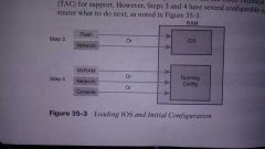
Cisco iOS boot sequence |
When our router powers on it follows these four steps
1. The router performs a power-on self-test process to discover the hardware components and verify they're working properly 2. The router copies a bootstrap program from ROM into RAM and runs the program 3. The bootstrap program decides which iOS image loads into RAM, once the iOS is loaded the bootstrap program gives control of the router to the IOS 4. Once the iOS is running it finds the startup config file and loads it into RAM as the running config |
|
|
|
The configuration register |
Routers use a configuration register to find configuration settings at boot time. It tells the router which IOS to load. The 16-bit for hex digits in the config register can be set to a variety of different parameters ( config-register command) - this command sets the configuration register values The last hex digit in the configuration register is called the boot field |
|
|
|
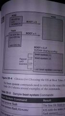
Boot system notes |
The point of the boot system commands and the boot field of the configuration register is to control which iOS Loads ( boot system flash) - the first file from system flash memory is loaded
(Boot system flash"filename") - the iOS with the name filename is loaded from system flash memory
(Boot system tftp "filename" 10.1.1.1) - the IRS with the name file name is loaded from the tftp server at address 10. 1. 1. 1 |
|
|
|
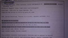
Using (SHOW Version commands) to verify new IOS image |
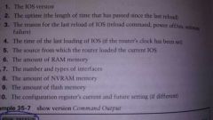
Important information found inside the show version commands |
|
|
|
Cisco password recovery/reset |
1. Boot ROMMON either by breaking into the boot process from the console or by removing Flash memory 2. Set the configuration register to ignore the startup config file (0x2142) 3. Boot the router with an iOS. The router boots with no configuration, now you can reach enable mode from the console without needing passwords |
|
|
|
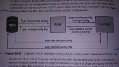
Using the COPY command to backup and restore configurations |
|
|
|
|
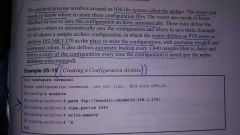
Using the archive process for a backup and restore configurations |
1.Create backup configurations called archives 2. Archive can be created based on configured timers automatically created each time someone saves the configuration 3. Perform a restore of the archive configuration by using the (configured replace command) |
|
|
|
Using the archive process for a backup and restore configurations |
1.Create backup configurations called archives 2. Archive can be created based on configured timers automatically created each time someone saves the configuration 3. Perform a restore of the archive configuration by using the (configured replace command) |
|