![]()
![]()
![]()
Use LEFT and RIGHT arrow keys to navigate between flashcards;
Use UP and DOWN arrow keys to flip the card;
H to show hint;
A reads text to speech;
177 Cards in this Set
- Front
- Back
|
Tool nomenclature |
be able to label parts of the cutting tool ex. size, shank, base, face, tool point, cutting edge, nose, flank |
|
|
flank wear |
wear on the refielf face of the tool |
|
|
crater wear |
wear on the rake face |
|
|
diffusion |
transfer of atoms across the interface between the workpiece and the cutting tool |
|
|
adhesion |
aslo known as attrition, occurs when 2 surfaces are brought together under high pressure and high temp |
|
|
chipping |
considered to be a catastrophic failure that occurs when a small piece breaks away from the cutting edges of the tool |
|
|
built-up edge |
(BUE) consisting of material from the workpiece, may collect on the cutting edges of the tool |
|
|
notching wear |
single groove formation that occurs simultaneously on the face and flank of the tool at the depth of the cut |
|
|
thermal crakcing |
appears as hairline cracks perpendicular to the cutting edge |
|
|
plastic deformation |
typically forms a bulge in the flank area of the tool |
|
|
tool life |
period of the cutting time that the tool can be used |
|
|
VT^n = C |
equation for the estimation of the tool life, Taylor's tool life eqaution V= cutting speed, ft/min (m/min) T= tool life, min n and C are the parameters that depend on factors such as feed rate, depth of cut, material, etc |
|
|
cutting tool materials |
high-speed steels cast cobalt alloys carbides coated carbides ceramics cubic boron nitride diamond |
|
|
high-speed steels |
(HSS) most highly alloyed of tool steels, used for drills, taps, broaches, and milling cutters |
|
|
Cast Cobalt Alloys |
composition of 38-53% Cobalt 30-33% Chromium 10-20% Tungsten -used for very large tools as opposed to solid carbide. |
|
|
benefits of carbide |
High hot hardnessHigh elastic modulus for toughnessGood thermal conductivityLow thermal expansion Coatings are typically used to increase wear resistance |
|
|
Coated Carbides |
coated carbide inserts have increased machining rates up to 5 or more times over rates of uncoated carbides |
|
|
CVD Inserts |
usually used to machine cast irons and steels |
|
|
DVD Inserts |
lower cutting speeds and for machining super alloys |
|
|
Ceramics |
common ceramic cutting tools include Silicon Nitride Aluminum Oxide mixed with ZrO2, TiC, orTiCN Aluminum Oxide mixed with Silicon Carbide whiskers SiAlOH-solid solution of Al2 O3 in Si3 N4 |
|
|
Cermet’s |
have sharp cutting edges, provide excellent surface finished, have wear resistance of 20 times higher than uncoated carbides Used for materials that produce a ductile chip- steels and ductile irons Can machine carbon, stainless steels, and ductile irons at high speeds while producing excellent surface finishes Work best in dry cutting applications Not recommended for rough machines |
|
|
Poly Crystalline Cubic Boron Nitride (PCBN) |
One of the hardest materials available |
|
|
Poly Crystalline Diamond (PCD) |
Micro sized diamonds crystals in a carbide substrate compacted together under high pressure and temperature |
|
|
Insert Geometry and Classification |
Key parameter is shape The geometry of the insert dictates the parameters of cutting High rake angle-better for rougher cuts Inserts size is determined by the largest circle that can be inscribed within its perimeter |
|
|
Tool selection |
Involves key factors Cutting physics and economics Goal is to choose a cutting tool shape, and material that minimizes cutting time, tool changes, tool cost, and setups while maximizing tool life, accuracy, and surface finish |
|
|
Cutting fluids |
Used extensively in cutting operations to reduce costs and enhance work piece characteristics Straight cutting oils Emulsifiable oils Chemical fluids Gaseous products |
|
|
Turning |
use of lathes and turning machines Engine lathes, turret lathes, and NC/CNC turning machines Engine Lathes-used for low-volume manufacturing runs |
|
|
turning components |
Bed- heavy metal casting supporting working parts of the lathe Headstock- housing for the headstock spindle-which is a hollow shaft supported by bearings that holds the work holding device (3 jaw chuck) Tailstock- support for straight and taper turning, drilling, and tapping Carriage- provides the longitudinal movement of the cutting tool along the bed Quick-change gear box- used for feeding-connects spindle to the carriage Provides uniform feed rates |
|
|
Drilling |
Produces holes by the relative motion of a rotating cutting tool and the work piece Machine types include vertical, multiple spindle (gang), radial, and turre *see notes for other info about drill, sizes, types, etc |
|
|
Types of drillings |
Counter drilling- enlarges existing holes Step drilling- when a hole with two or more diameters is cut with the same drill Counter boring- enlarging a hole to a specific depth Counter sinking- produces angular openings at the end of a hole Reaming- used to produce accurate hole (size and roundness) with good surface finish Center drilling- used to produce a tapered hole at the end of the work piece to accommodate a center in the tailstock or headstock or a lathe. Also used for accurately marking the location of a hole to prevent a twist drill from wandering |
|
|
Drill sizes |
Size of drill designates the nominal diameter of its body and hole it is intended to produce Standard drills are available in numbered, lettered, and fractional inch and millimeter sizes Fractional sizes come in 1/64th inch steps up to 1 ¾” and larger steps above that to over 3” Number and letter drills range from .0059-.4130 in. in diameter between the fractional sizes |
|
|
twist drills |
common type of cutting tool |
|
|
Milling |
Machining process for removing material by relative motion between a work piece and rotating cutter having multiple cutting edges |
|
|
Milling Types |
standard vertical or horizontal knee-and column computer numerical control CNC machining centers |
|
|
General milling methods |
Slab milling Face milling End milling |
|
|
Styles of milling |
Conventional/up milling- cutter is opposed by the feed of the work piece Require more feeding force, generates higher cutting temps, produces rougher finish, tens to life work piece out of the vise or fixture Climb/down milling Pulls work piece a long, reduces feeding forceLower cutting temp, longer tool life, smoother finish |
|
|
Band Sawing |
Using a long endless band with many small teeth traveling over two or more wheels in one direction Three major types of tooth geometries Standard Hook tooth Skip tooth |
|
|
Pitch |
number of teeth per inch Determined by the thickness of the material Optimum pitch is ensured if at least 6 teeth are in contact with the same work piece at all times during sawing Too few teeth- cause teeth to be stripped Too many teeth- cause gullets to clog and results in rubbing instead of cutting |
|
|
Tooth set |
projection of the teeth from the sides of the band to provide cutting clearance Raker set Wave set Straight (alternate) set *see notes for materials used |
|
|
Grinding |
Process used when high surface finish and high dimensional accuracy are needed Time consuming and expensive, used when chip doesn't work for harder materials |
|
|
Surface grinders Cylindrical grinders |
horizontal or vertical spindle with either a traverse or rotary table both internal or external |
|
|
Wheel selections |
Abrasive type Grain size Bon Grade Structure |
|
|
High Speed Machining (HSM) |
Faster metal removal rates by running high spindle speeds and feed rates but taking lighter cuts 1. Speed and productivity 2. Better surface finish to eliminate or reduce the need for polishing basic spindle speeds of 10,000 rpm, 400 in/min or greater feed rates, and 2-5 axis machine control |
|
|
Look ahead software |
accelerate or decelerate the tool for more effective cutting Post processor- translates output from tool path software to specific machine codes Operator- responsible for establishing valid base parameters, tool selection, and then running them |
|
|
Boring |
Precision machining process for generating internal cylindrical forms by removing metal with a single-point tools with multiple cutting edges |
|
|
Broaching |
Traditional machining process used for special surface machining applications |
|
|
Broaching |
set of cutting teeth that have cutting teeth at different heights to progressively remove material from the surface 2 types Internal broaches- finish all or part of internal surfaces, keyways, or splines External broaches- machine-in specialized features or contours on the work pieces external surface |
|
|
Thread cutting |
Threads may be cut with single point tools on a lathe, or with multiple-tooth cutters that include taps, dies, and milling cutters DIE- used for external threads Tap- shank with several radically placed cutting teeth used to thread holes Can be operated by machine or by hand |
|
|
Non-traditional Machining Processes |
used when conventional methods are incapable, impractical, or uneconomical because of special material properties, work piece, complexities, or lack of inherent rigidity |
|
|
water jet machining |
removes material and procedures a narrow kerf by cutting action of a fine, high-pressure, high velocity, stream of water or water based fluid with additives |
|
|
abrasive water jet machining |
contains abrasive particles such as aluminum oxide or silicon carbide |
|
|
Electrochemical Machining (ECM) |
widely employed method of removing metal without the use of mechanical or thermal energy |
|
|
Electrical Discharge Machining (EDM) |
based upon the erosion effect of electrical sparks occurring between two electrodes |
|
|
Laser Beam Machining |
used in many applications such as drilling, cutting, heat treating, scribing, and welding. |
|
|
Hot Forming |
Any metal forming operation done above the metal’s recrystallization temperature |
|
|
Cold Forming |
Any metal forming operation done below the metal’s recrystallization temperature. |
|
|
Warm Forming |
Cross between hot forming and cold forming, less heating than Hot Forming, less energy than Cold Forming |
|
|
Rolling |
Highly productive, continuous forming process that can be done hot or cold. |
|
|
Pickling |
Immersing the steel in a bath typically containing hydrochloric acid and inhibiters to prevent the acid from eroding the steel underneath |
|
|
Thread Rolling |
Cold rolling process for producing threads on cylindrical or conical work pieces. |
|
|
Extrusion |
Plastic deformation process in which material is forced under pressure through one or more die orifices |
|
|
Direct Extrusion |
Billet form loaded into a thick-walled chamber, and pushed through a stationary die to form desired shape |
|
|
Indirect Extrusion |
Billet remains stationary, relative to the container wall while the die is pushed into the billet. |
|
|
Hydrostatic Extrusion |
Hydraulic fluid is used in the ram cavity and, when pressurized, force is exerted not only to push the material through the die, but also away from the walls of the cavity. |
|
|
Forging |
Controlled plastic deformation or working of metals into pre-determined shapes by means of pressure or impact blows, or a combination of the two. |
|
|
Open-die forming |
Simple shapes & rings, rings on discs of shafts |
|
|
impression-Die Forging (Closed-Die Forging) |
Work piece is placed between two dies containing the impression of the shape to be forged |
|
|
precision Forging (Flashless Forging) |
does not depend on flash to fill out part |
|
|
Coining |
Produces fine details of parts in both top and bottom surfaces. |
|
|
Upsetting |
Increasing the diameter of a round work piece by decreasing its length |
|
|
Wire and Bar Drawing |
reduces cross-sectional area of a wire or bar by pulling it through a die |
|
|
Hydroforming |
Uses hydrostatic pressure to move the work piece material so it will conform to the shape of a metal die. |
|
|
High Energy Rate Forming (HERF) |
Explosive forming: done with low and high explosives and gas mixes Electrohydraulic forming Electromagnetic forming |
|
|
Shearing |
Process of mechanically cutting sheet metal with application of shear force. |
|
|
Punching |
Sheared slug is discarded, also known as piercing ex. holes |
|
|
Blanking |
Sheared slug is saved, remainder is scrap ex. cookies |
|
|
Notching |
Involves removing metal from edges of ports Similar to punching, but only around perimeter of part |
|
|
Lancing |
Combines cutting and forming in one step. Creates hole without completely separating the material |
|
|
Fine blanking |
Produces very smooth and square edges |
|
|
Nibbling |
Punches out a series of overlapping holes to produce an elongated slot |
|
|
Dinking |
Used for materials lie soft metals, leather, paper, and rubber, which are difficult to cut with conventional shearing. Similar to cookie-cutter and cuts material into wood block. |
|
|
Shear Strength |
Capability of a material to resist shearing. Directly proportional to its hardness and tensile strength. Clearance between the punch and the die is important. Too much clearance causes plastic deformation before it is out. |
|
|
Bending |
Made to gain rigidity and produce a part of a desired shape to perform a particular function. |
|
|
Flange Bending |
Forming operation in which a narrow strip at the edge of the sheet is bent down along a straight or curved line |
|
|
Hemming |
Creating a flange that has been bent 180º or more. |
|
|
Roll bending |
Curving material into cylinders or cylindrical segments. |
|
|
Drawing |
Process of cold forming a flat pre-cut metal blank into a hollow vessel without wrinkling, thinning, or fracturing |
|
|
Presses and Dies |
Manual Presses: Hand or Foot- Operated through levers, screws or gears. Mechanical Press: Utilize flywheel energy. Hydraulic Press: Uses fluid power principles by means of pumps, valves, or intensities. |
|
|
Metal Spinning |
Specialized metal-forming process used for hollow products, that can be turned to produce desired shapes |
|
|
Powder Metallurgy (PM) |
a metal-working process for forming near-net shape, precision metal components, and shapes from metal powders Powder manufacturing Blending Compacting Sintering |
|
|
Powder manufacturing |
Common method is called melt atomization |
|
|
Blending |
Oversize and fine particles are filtered out |
|
|
Compacting |
Controlled amount of product is fed into a precision die |
|
|
Sintering |
Develops metallurgic bands among powder particles. |
|
|
Secondary Processes |
Re-Pressing Infiltrating w/ other metals, or impregnated with oils or resins. |
|
|
Casting |
process in which molten metal is poured or injected into a cavity and allowed to solidify, taking on the shape of the cavity. |
|
|
Casting defects |
misrun, cold shut, porosity, shrinkage, hot tear, core shift, and inclusions. |
|
|
Cope Drag |
Upper half of the mold. Lower half of the mold. |
|
|
Cores Sprue |
Used to create internal cavities in castings (Made of sand or metal). Channel in which the metal enters the mold |
|
|
Runner Gates |
Leads metal through the mold Attach runner(s) to the mold cavity. |
|
|
riser |
a reservoir connected to the mold cavity to feed liquid to the casting to prevent shrinkage as it solidifies. |
|
|
Green Sand Casting |
A mold is compacted around a pattern with a sand-clay-water mixture. multiple/single use |
|
|
Shell Molding |
Higher degree of accuracy and surface finish than sand casting. multiple/single use |
|
|
Investment casting |
Wax pattern is dipped into a ceramic slurry that hardens into a ceramic shell around that pattern. single use |
|
|
Lost Foam Casting |
Process of casting, using expanded polystyrene foam patterns to eliminate the need for traditional mold cavities single use |
|
|
Permanent mold casting |
Pouring molten metal under pressure of gravity lead or a low-pressure feed system into a static mold. multi-use |
|
|
Die Casting |
Molten metal is forced under pressure into metal molds or dies. |
|
|
Hot Chamber |
limited to 2000-4000 psi |
|
|
Cold Chamber |
Molten metal is located in separate holding furnace |
|
|
Welding |
means of joining materials by concentrating heat and or pressure at the joint to cause coalescence of the adjoining areas |
|
|
Fusion welding |
parent materials and potentially a filler material melt together to form the welding joint |
|
|
Solid state welding |
work pieces are joined by the application of heat and pressure or just by pressure. |
|
|
Oxyfuel gas welding |
Uses oxygen and acetylene to create heat to weld |
|
|
Oxyfuel gas cutting |
Thermal cutting process that can cut straight or varying lines in steel (2 in thick or less) Rapid burning or oxidation of iron in the presence of high-purify oxygen Use of cutting tip |
|
|
Shielded Metal Arc Welding (SMAW) |
Electric arc creates heat through an consumable electrode that has a flux coating |
|
|
Gas Metal Arc Welding (GMAW) |
Joining metal by arc between continuous wire and work piece |
|
|
Metal Inert Gas (MIG) |
Direct current process Amperage determined by wire feed speed |
|
|
Gas Tungsten Arc Welding (DTAW) |
Joining metals by an arc between the work piece and a tungsten (non-consumable) electrode |
|
|
Plasma Arc Welding (PAW) |
Electrode is recessed as opposed to GTAW where it is extended from the tip Can also be used as a cutting process for ferrous metals |
|
|
Arc Welding Defects |
Weld Splatter-Caused By: Excessive welding current Wrong electrode Wrong electrode polarity Too large an electrode Improper electrode position Arc blow Excessive arc length Low gas flow Contaminated weld joint surfaces |
|
|
Undercut-Caused By |
High welding currents Fast travel speeds Improper electrode positions or manipulation Excessive arc length Too large of electrode |
|
|
Incomplete Fusion-Lack of penetration |
Improper current Improper welding technique Improper joint preparation Wrong electrode size Improper electrode manipulation of welding position |
|
|
cause of cracks |
Porosity-surface holes, gas pockets Incomplete cleaning Long arc length Moisture |
|
|
Slag Inclusion-Usually SMAW |
Slag becomes trapped in weld resulting in weld failure |
|
|
Overlap |
Caused by improper welding technique Slow speed Poor join prep |
|
|
Distortion |
Residual stresses bend, etc. |
|
|
Electric Resistance Welding |
Weld using resistance of welding current and pressure Spot welding |
|
|
Solid-State Welding |
Welding joint produced without melting the parent material or filler material ultrasonic friction |
|
|
Unique Welding Processes |
Laser-beam Welding Electron Beam Welding Thermit Welding Weld bonding |
|
|
Laser-beam Welding |
Fusion joining process that produces coalescence of metals with heat generated by the absorption of a concentrated, coherent light beam. |
|
|
Electron Beam Welding |
Uses high-intensity beams of electrodes to melt the metals together Produces weld with high depth to width ratio Needs use of vacuum for production capacities Can produce harmful radiation |
|
|
Thermit Welding |
Joining of metals by heating with a superheated molten metal produced by a reaction between a metal oxide and aluminum Used for joining heavy and/or complex cross-sections not able to be welded by other welding processes Common application welding rails for trains |
|
|
Weld bonding |
Combination of resistance spot or seam welding and adhesive bonding Improved fatigue life and durability Provides corrosion resistance |
|
|
Brazing |
Group of joining processes in which filler metal melts above 840 degrees F and below the melting temp of the metals being joined |
|
|
Soldering |
Group of joining processes using a filler metal which melts below 840 degrees F and the metals being joined |
|
|
Mechanical Fasteners |
Integral Fasteners Formed areas of a component that function by interfering or interlocking with other areas of the assembly Discrete Fasteners Threaded fasteners including bolts, nuts, screws, and other fasteners such as rivets, pins and retaining rings |
|
|
Threaded Fasteners |
bolts, studs, nuts, screws, etc |
|
|
Cap Screws |
Manufactured to close tolerances and designed for applications requiring high tensile strengths |
|
|
Set Screws |
Hardened fasteners generally used to hold pulleys, gears, and other components on shafts |
|
|
SEMS (Screw and Washer Assemblies) |
Washer is placed on screw blank before threads are formed then becoming permanent part of assembly |
|
|
Tapping Screws |
Cut or formatting threads when driven into holes Self-drilling, self-piercing, special tapping screws Typically used on thin materials |
|
|
screw Pitch |
Distance parallel to the axis from any point on a screw thread to a corresponding point on the next thread |
|
|
Lead |
Distance a screw has only one continuous thread on its surface (most common) lead=pitch |
|
|
Major Diameter |
Diameter of a cylinder on which the crest of an external thread or the root of an internal thread lies |
|
|
Minor Diameter |
Diameter of a cylinder on which the root of an external thread or the crest of an internal thread lies |
|
|
Pitch Diameter |
Diameter of a cylinder that cuts the threads where the width of the threads is equal to the width of the space between the threads |
|
|
Screw Standards |
Creation of a standard form for threads Unified screw thread form Unified National Coarse (UNC) Unified National Fine (UNF) Unified National Extra Fine (UNEF) American National Standard Taper Pipe Thread (NPT) Each series specific the threads per inch (tpi) and basic dimensions and tolerances for cretin nominal inch size diameters Thread class Designates fit between internal and external mating threads Metric thread designation begins with “m” following nominal size in mm after the times sign is the pitch |
|
|
UNC |
Unified National Coarse |
|
|
UNF |
Unified National Fine |
|
|
UNEF |
Unified National Extra Fine |
|
|
NPT |
American National Standard Taper Pipe Thread |
|
|
tpi |
threads per inch |
|
|
Rivets |
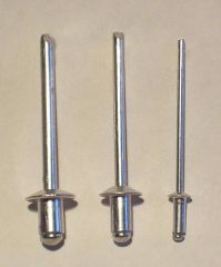
angel blades One piece, unthreaded, permanent fastener consisting of a head and a body quick, easy cheap not as strong |
|
|
Pins |
Provide simple and low cost method of mechanical fastening |
|
|
Dowel Pins |
Used extensively in the production of machines, tools, dies, and fixtures, to retain parts in fixed positions or preserve alignments |
|
|
Tapered Pins |
Used to position parts or transmit low torque forces |
|
|
Clevis Pins |
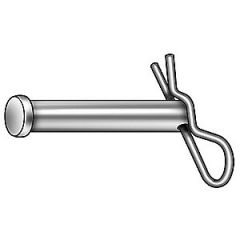
Solid pins with cylindrical heads at one end and a drilled hole for a cotter pin at the other |
|
|
Cotter (Split) Pins |
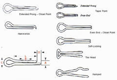
Double bodied pins formed form half round wire |
|
|
Spring Pins |
Made in slotted split tube and coiled designs |
|
|
Retaining Rings (Snap Rings) |
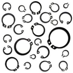
Used for providing shoulders and/or bearing surfaces for locating or limiting the movement of parts on shafts or inside holes |
|
|
Adhesive Bonding |
Advantages Join dissimilar materials Provide strong joints Save weight Reduce assembly cost Distribute stress uniformity across the bon line Significantly reducing the stress concentrations that cause fatigue and failure Thin and fragile materials not suitable for mechanical fasteners or welding can be joined Adhesives seal in addition to joining |
|
|
Deburring processes |
Hard Deburring Mass finishing Tumbling and vibratory finishing Abrasive Flow Machining Semi-solid abrasive media is forced or extruded through a work piece passage Thermal energy method Used of intense and instantaneous heat to burn or oxidize burrs Electrochemical Deburring Use of electrochemical processes to remove burrs Wire Brushing |
|
|
Honing |
Process used to achieve final sizing, correct contour errors, and provide desired surface finishes Used primarily for burring operations |
|
|
Lapping |
Abrasive machining process used for highly accurate stock removal under .001 in and five surface finishes |
|
|
Shot Peening |
Cold working of a metal surface by a stream of spherical shot particles applied to a surface at high velocity under carefully controlled conditions |
|
|
Electro Polishing |
Used to enhance surface finish and appearance of a work piece |
|
|
Electro Plating |
Work piece is made cathodic in a solution containing the ions of the metal being deposited |
|
|
Anodizing |
Forms a stable film or coating on a metals surface Used for abrasion and water resistance |
|
|
Polymer Coatings |
Liquid organic Coatings Power Coating |
|
|
Extrusion |
Continuous operation that forces hot plasticized material through a die opening to produce the desired shape |
|
|
Extrusion Categorized by |
general shape of the products they produce Profile Extrusions Pipe Extrusions Sheet Extrusions Film Extrusions Filament Extrusion Wire Coating |
|
|
Blow molding |
Process for shaping thermoplastic materials into one-piece, hollow articles by heat and air pressure extrusion and injection(stronger for carbonated drinks) ext=milk jugs inj=soda bottles |
|
|
Injection molding |
Use of high pressure to deliver a material quantity of heated and plasticized material into a relatively cool mold which solidifies the plastics material |
|
|
Thermoforming Plastic Sheet and Film |
Heating plastic sheet or film to its processing temperature and forcing the hot, flexible material against the contours of a mold vaccuum |
|
|
Rotational Molding |
Process for forming hollow plastic parts |
|
|
Compression Molding |
Heated to plasticize material than are placed under pressure to form desired shape |
|
|
Transfer Molding |
like compression, but from one cavity to another |