![]()
![]()
![]()
Use LEFT and RIGHT arrow keys to navigate between flashcards;
Use UP and DOWN arrow keys to flip the card;
H to show hint;
A reads text to speech;
222 Cards in this Set
- Front
- Back
|
the units of capacitance are equivalent to |
C^2/J |
|
|
A farad is the same as a |
C/V |
|
|
A capacitor C “has a charge Q”. The actual charges on its plates are: |
Q,−Q |
|
|
Each plate of a capacitor stores a charge of magnitude 1 mC when a 100-V potential differenceis applied. The capacitance is |
10μF |
|
|
to charge a 1-F capacitor with 2 C requires a potential difference of: |
2 V |
|
|
The capacitance of a parallel-plate capacitor with plate areaAand plate separationdis givenby |
E0*A/d |
|
|
The capacitance of a parallel-plate capacitor is: |
proportional to the plate area |
|
|
the plate areas and plate separations offive parallel plate capacitors are capacitor 1: areaA0, separation d0 capacitor 2: area 2A0, separation 2d0 capacitor 3: area 2A0, separation d0/2 capacitor 4: areaA0/2, separation 2d0 capacitor 5: areaA0, separation d0/2 Rank these according to their capacitances, least to greatest. |
4, 1 and 2 tie, then 5, 3 |
|
|
the capacitance of a parallel-plate capacitor can be increased by: |
decreasing the plate separation |
|
|
If both the plate area and the plate separation of a parallel-plate capacitor are doubled, the capacitance is: |
unchanged |
|
|
if the plate area of an isolated charged parallel-plate capacitor is doubled: |
the potential difference is halved |
|
|
If the plate separation of an isolated charged parallel-plate capacitor is doubled: |
A. the electricfield is doubled B. the potential difference is halved C. the charge on each plate is halved D. the surface charge density on each plate is doubled ->E. none of the above |
|
|
Pulling the plates of an isolated charged capacitor apart |
ncreases the potential difference |
|
|
If the charge on a parallel-plate capacitor is doubled: |
the electric field is doubled |
|
|
A parallel-plate capacitor has a plate area of 0.2m^2 and a plate separation of 0.1mm. Toobtain an electricfield of 2.0×10^6V/m between the plates, the magnitude of the charge oneach plate should be: |
7.1×10^−6C |
|
|
A parallel-plate capacitor has a plate area of 0.2m^2and a plate separation of 0.1 mm. If thecharge on each plate has a magnitude of 4×10⁻⁶C the potential difference across the platesis approximately: |
2×10^2V |
|
|
The capacitance of a spherical capacitor with inner radius a and outer radius b is proportional to |
ab/(b-a) |
|
|
the capacitance of a single isolated spherical conductor with radiusRis proportional to |
R |
|
|
Two conducting spheres have radii of R1 and R2, with R1 greater than R2. If they are farapart the capacitance is proportional to |
ncreasing both the radius of the inner cylinder and the length |
|
|
A battery is used to charge a series combination of two identical capacitors. If the potentialdifference across the battery terminals is V and total charge Q flows through the battery during the charging process then the charge on the positive plate of each capacitor and the potential difference across each capacitor are: |
Q and V/2 respectively |
|
|
A battery is used to charge a parallel combination of two identical capacitors. If the potentialdifference across the battery terminals isVand total chargeQflows through the battery duringthe charging process then the charge on the positive plate of each capacitor and the potentialdifference across each capacitor are |
Q/2 and V respectively |
|
|
A 2-μFanda1-μF capacitor are connected in series and a potential difference is applied acrossthe combination. The 2-μF capacitor has |
half the potential difference of the 1-uF capacitor |
|
|
A 2-μFanda1-μF capacitor are connected in parallel and a potential difference is appliedacross the combination. The 2-μF capacitor has: |
twice the charge of the 1-μF capacitor |
|
|
Let Q denote charge,V denote potential difference, and U denote stored energy. Of thesequantities, capacitors in series must have the same |
Q only |
|
|
LetQdenote charge,Vdenote potential difference, andUdenote stored energy. Of thesequantities, capacitors in parallel must have the same: |
V only |
|
|
CapacitorsC1andC2are connected in parallel. The equivalent capacitance is given by |
C1+C2 |
|
|
CapacitorsC1andC2are connected in series. The equivalent capacitance is given by |
C1C2/(C1+C2) |
|
|
CapacitorsC1andC2are connected in series and a potential difference is applied to thecombination. If the capacitor that is equivalent to the combination has the same potentialdifference, then the charge on the equivalent capacitor is the same as: |
the charge onC1 |
|
|
CapacitorsC1andC2are connected in parallel and a potential difference is applied to thecombination. If the capacitor that is equivalent to the combination has the same potentialdifference, then the charge on the equivalent capacitor is the same as |
the sum of the charges onC1andC2 |
|
|
CapacitorsC1andC2are connected in parallel and a potential difference is applied to thecombination. If the capacitor that is equivalent to the combination has the same potentialdifference, then the charge on the equivalent capacitor is the same as |
he sum of the charges onC1andC2 |
|
|
Two identical capacitors are connected in series and two, each identical to thefirst, are con-nected in parallel. The equivalent capacitance of the series connection is ____ the equivalentcapacitance of parallel connection |
1/4 |
|
|
Two identical capacitors, each with capacitanceC, are connected in parallel and the combi-nation is connected in series to a third identical capacitor. The equivalent capacitance of thisarrangement is |
2C/3 |
|
|
A 2-μFanda1-μF capacitor are connected in series and charged from a battery. They storechargesPandQ, respectively. When disconnected and charged separately using the samebattery, they have chargesRandS, respectively. Then |
R>S>Q=P |
|
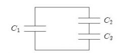
CapacitorC1is connected alone to a battery and charged until the magnitude of the chargeon each plate is 4.0×10⁻⁸C. Then it is removed from the battery and connected to two othercapacitorsC2andC3, as shown. The charge on the positive plate ofC1is then 1.0×10⁻⁸C.The charges on the positive plates ofC2andC3are |
q2 = 3*10^-8C & q3 = 3*10^-8C |
|
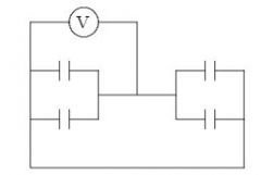
Each of the four capacitors shown is 500μF. The voltmeter reads 1000 V. The magnitude ofthe charge, in coulombs, on each capacitor plate is |
0.5 |
|
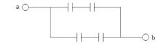
The diagram shows four 6-μF capacitors. The capacitance between points a and b is |
6uF |
|
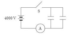
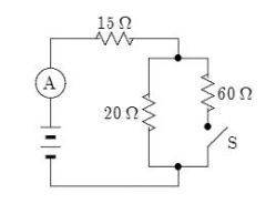
Each of the two 25-μF capacitors shown is initially uncharged. How many coulombs of chargepass through the ammeter A after the switch S is closed? |
0.20 |
|
|
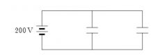
A 20-F capacitor is charged to 200 V. Its stored energy is |
0.4 J |
|
|
charged capacitor stores 10 C at 40 V. Its stored energy is: |
200J |
|
|
A 2-μF and a 1-μF capacitor are connected in series and charged by a battery. They storeenergiesPandQ, respectively. When disconnected and charged separately using the samebattery, they store energiesRandS, respectively. Then: |
R>S>Q>P |
|
|
The quantity (1/2)E0*E^2has the significance of: |
energy/volume |
|
|
Capacitors A and B are identical. Capacitor A is charged so it stores 4 J of energy and capacitorB is uncharged. The capacitors are then connected in parallel. The total stored energy in thecapacitors is now: |
2J |
|
To store a total of 0.040 J of energy in the two identical capacitors shown, each should have acapacitance of: |
1 uJ |
|
|
A battery is used to charge a parallel-plate capacitor, after which it is disconnected. Then theplates are pulled apart to twice their original separation. This process will double the: |
stored energy |
|
|
A parallel-plate capacitor has a plate area of 0.3m2and a plate separation of 0.1 mm. If thecharge on each plate has a magnitude of 5×10⁻⁶C then the force exerted by one plate on theother has a magnitude of about: |
5N |
|
|
A certain capacitor has a capacitance of 5.0μF. After it is charged to 5.0μC and isolated, theplates are brought closer together so its capacitance becomes 10μF. The work done by theagent is about: |
-1.25*10^(-6) |
|
|
A dielectric slab is slowly inserted between the plates of a parallel plate capacitor, while thepotential difference between the plates is held constant by a battery. As it is being inserted: |
the capacitance and the charge on the positive plate increase but the potential differencebetween the plates remains the same |
|
|
An air-filled parallel-plate capacitor has a capacitance of 1 pF. The plate separation is thendoubled and a wax dielectric is inserted, completelyfilling the space between the plates. As aresult, the capacitance becomes 2 pF. The dielectric constant of the wax is: |
4 |
|
|
One of materials listed below is to be placed between two identical metal sheets, with no, airgap, to form a parallel-plate capacitor. Which produces the greatest capacitance? |
material of thickness 0.5 mm and dielectric constant 11 |
|
|
Two capacitors are identical except that one isfilled with air and the other with oil. Bothcapacitors carry the same charge. The ratio of the electricfieldsEair/Eoilis: |
between 1 and infinity |
|
|
a parallel-plate capacitor, with air dielectric, is charged by a battery, after which the batteryis disconnected. A slab of glass dielectric is then slowly inserted between the plates. As it isbeing inserted: |
a force attracts the glass into the capacitor |
|
|
Two parallel-plate capacitors with the same plate separation but different capacitance areconnected in parallel to a battery. Both capacitors arefilled with air. The quantity that isNOT the same for both capacitors when they are fully charged is: |
charge on the positive plate |
|
|
Two parallel-plate capacitors with the same plate area but different capacitance are connectedin parallel to a battery. Both capacitors arefilled with air. The quantity that is the same forboth capacitors when they are fully charged is: |
potential difference |
|
|
Two parallel-plate capacitors with different plate separation but the same capacitance areconnected in series to a battery. Both capacitors arefilled with air. The quantity that is NOTthe same for both capacitors when they are fully charged is: |
electricfield between the plates |
|
|
Two parallel-plate capacitors with different capacitance but the same plate separation areconnected in series to a battery. Both capacitors arefilled with air. The quantity that is thesame for both capacitors when they are fully charged is: |
charge on the positive plate |
|
|
A car battery is rated at 80 A·h. An ampere-hour is a unit of: |
charge |
|
|
Current has units |
C/s |
|
|
Current has unit |
ampere |
|
|
The units of resistivity are: |
ohm-meter |
|
|
The rate at which electrical energy is used may be measured in |
watt |
|
|
Energy may be measured in |
watt-second |
|
|
Which one of the following quantities is correctly matched to its unit? |
Potential difference - J/C |
|
|
Current is a measure of: |
amount of charge that moves past a point per unit time |
|
|
A 60-watt light bulb carries a current of 0.5 A. The total charge passing through it in one houris: |
1800C |
|
|
A 10-ohm resistor has a constant current. If 1200 C of chargeflow through it in 4 minutes whatis the value of the current? |
15A |
|
|
Conduction electrons move to the right in a certain wire. This indicates that: |
he current density and electricfield both point left |
|
|
Two wires made of different materials have the same uniform current density. They carry thesame current only if: |
heir cross-sectional areas are the same |
|
|
A wire with a length of 150 m and a radius of 0.15 mm carries a current with a uniform currentdensity of 2.8×10⁷A/m2. The current is: |
2A |
|
|
n a conductor carrying a current we expect the electron drift speed to be: |
much less than the average electron speed |
|
|
Two substances are identical except that the electron mean free time for substance A is twicethe electron mean free time for substance B. If the same electricfield exists in both substancesthe electron drift speed in A is |
twice that in B |
|
|
The current is zero in a conductor when no potential difference is applied because |
or every electron with a given velocity there is another with a velocity of equal magnitudeand opposite direction. |
|
|
The current density is the same in two wires. Wire A has twice the free-electron concentrationof wire B. The drift speed of electrons in A is: |
half that of electrons in B |
|
|
copper contains 8.4×1028free electrons/m3. A copper wire of cross-sectional area 7.4×10⁻⁷m2carries a current of 1 A. The electron drift speed is approximately: |
10−4m/s |
|
|
If J is the current density anddnAis a vector element of area then the integral$nJ·dnAover anarea represents: |
the current through the area |
|
|
If the potential difference across a resistor is doubled: |
only the current is doubled |
|
|
five cylindrical wires are made of the same material. Their lengths and radii are wire 1: lengthf, radiusr wire 2: lengthf/4, radiusr/2 wire 3: lengthf/2, radiusr/2 wire 4: lengthf, radiusr/2 wire 5: length 5f, radius 2r Rank the wires according to their resistances, least to greatest. |
1 and 2 tie, then 5, 3, 4 |
|
|
Of the following, the copper conductor that has the least resistance is: |
hick, short and cool |
|
|
A cylindrical copper rod has resistanceR. It is reformed to twice its original length with nochange of volume. Its new resistance is: |
4R |
|
|
The resistance of a rod does NOT depend on: |
he shape of its (fixed) cross-sectional area |
|
|
A certain wire has resistanceR. Another wire, of the same material, has half the length andhalf the diameter of thefirst wire. The resistance of the second wire is: |
2R |
|
|
A nichrome wire is 1 m long and 1×10⁻⁶m2in cross-sectional area. When connected to apotential difference of 2 V, a current of 4 A exists in the wire. The resistivity of this nichromeis: |
5×10⁻⁷Ω·m |
|
|
Two conductors are made of the same material and have the same length. Conductor A is asolid wire of diameter 1 m. Conductor B is a hollow tube of inside diameter 1 m and outsidediameter 2 m. The ratio of their resistance,RA/RB, is: |
3 |
|
|
Conductivity is: |
expressed in (Ω·m)−1 |
|
|
A certain sample carries a current of 4 A when the potential difference is 2 V and a current of10 A when the potential difference is 4 V. This sample: |
has a resistance of 0.5Ωat 1 V |
|
|
A current of 0.5 A exists in a 60-ohm lamp. The applied potential difference is: |
30V |
|
|
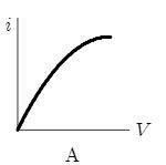
Which of the following graphs best represents the current-voltage relationship of an incandes-cent light bulb? |
|
|
|
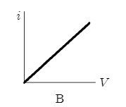
Which of the following graphs best represents the current-voltage relationship for a device thatobeys Ohm’s law? |
|
|
|
Two wires are made of the same material and have the same length but different radii. Theyare joined end-to-end and a potential difference is maintained across the combination. Of thefollowing the quantity that is the same for both wires is: |
current |
|
|
For an ohmic substance the resistivity is the proportionality constant for: |
urrent density and electricfield |
|
|
For an ohmic resistor, resistance is the proportionality constant for: |
urrent and potential difference |
|
|
For an ohmic substance, the resistivity depends on |
he electron mean free time |
|
|
For a cylindrical resistor made of ohmic material, the resistance does NOT depend on: |
the current |
|
|
For an ohmic substance, the electron drift velocity is proportional to: |
the electricfield in the sample |
|
|
You wish to triple the rate of energy dissipation in a heating device. To do this you couldtriple: |
he resistance keeping the current the same |
|
|
A student kept her 60-watt, 120-volt study lamp turned on from 2:00 PM until 2:00 AM. Howmany coulombs of charge went through it? |
21,600 |
|
|
Aflat iron is marked “120 V, 600 W”. In normal use, the current in it is: |
5 A |
|
|
An certain resistor dissipates 0.5 W when connected to a 3 V potential difference. When con-nected to a 1 V potential difference, this resistor will dissipate: |
0.056 W |
|
|
An ordinary light bulb is marked “60 W, 120 V”. Its resistance is: |
240ohm |
|
|
The mechanical equivalent of heat is 1 cal = 4.18 J. The specific heat of water is 1 cal/g·K. Anelectric immersion water heater, rated at 400 W, should heat a kilogram of water from 10◦Cto 30◦C in about: |
3.5min |
|
|
It is better to send 10,000 kW of electric power long distances at 10,000 V rather than at 220 Vbecause: |
here is less heating in the transmission wires |
|
|
Suppose the electric company charges 10 cents per kW·h. How much does it cost to use a125 W lamp 4 hours a day for 30 days? |
$1.50 |
|
|
A certain x-ray tube requires a current of 7 mA at a voltage of 80 kV. The rate of energydissipation (in watts) is: |
560 |
|
|
The mechanical equivalent of heat is 1 cal = 4.18 J. A heating coil, connected to a 120-V source,provides 60,000 calories in 10 minutes. The current in the coil is: |
3.5A |
|
|
You buy a “75 W” light bulb. The label means that: |
none of the above |
|
|
A current of 0.3 A is passed through a lamp for 2 minutes using a 6-V power supply. The energydissipated by this lamp during the 2 minutes is: |
216 J |
|
|
“The sum of the currents into a junction equals the sum of the currents out of the junction” isa consequence of: |
conservation of charge |
|
|
The sum of the emf’s and potential differences around a closed loop equals zero” is a conse-quence of: |
conservation of energy |
|
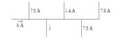
A portion of a circuit is shown, with the values of the currents given for some branches. Whatis the direction and value of the currenti? |
↓,6A |
|
|
Four wires meet at a junction. Thefirst carries 4 A into the junction, the second carries 5 Aout of the junction, and the third carries 2 A out of the junction. The fourth carries: |
3 A into the junction |
|
|
In the context of the loop and junctions rules for electrical circuits a junction is: |
where three or more wires are joined |
|
|
for any circuit the number of independent equations containing emf’s, resistances, and currentsequals: |
t he number of branches |
|
|
If a circuit hasLclosed loops,Bbranches, andJjunctions the number of independent loopequations is: |
B−J+1 |
|
|
A battery is connected across a series combination of two identical resistors. If the potentialdifference across the terminals isVand the current in the battery isi, then: |
the potential difference across each resistor isV/2 and the current in each resistor is i |
|
|
A battery is connected across a parallel combination of two identical resistors. If the potentialdifference across the terminals isVand the current in the battery isi, then: |
the potential difference across each resistor isVand the current in each resistor isi/2 |
|
|
A total resistance of 3.0Ωis to be produced by combining an unknown resistorRwith a 12Ωresistor. What is the value ofRand how is it to be connected to the 12Ωresistor? |
4.0Ω, parallel |
|
|
By using only two resistors,R1andR2, a student is able to obtain resistances of 3Ω,4Ω,12Ω,and 16Ω. The values ofR1andR2(in ohms) are: |
4, 12 |
|
|
Four 20-Ωresistors are connected in parallel and the combination is connected to a 20-V emfdevice. The current in the device is: |
4.0A |
|
|
Four 20-Ωresistors are connected in parallel and the combination is connected to a 20-V emfdevice. The current in any one of the resistors is: |
1.0A |
|
|
Four 20-Ωresistors are connected in series and the combination is connected to a 20-V emfdevice. The current in any one of the resistors is: |
0.25 A |
|
|
Four 20-Ωresistors are connected in series and the combination is connected to a 20-V emfdevice. The potential difference across any one of the resistors is: |
5 V |
|
|
Nine identical wires, each of diameterdand lengthL, are connected in parallel. The combina-tion has the same resistance as a single similar wire of lengthLbut whose diameter is: |
3d |
|
|
Nine identical wires, each of diameterdand lengthL, are connected in series. The combinationhas the same resistance as a single similar wire of lengthLbut whose diameter is: |
d/3 |
|
|
two wires made of the same material have the same lengths but different diameters. They areconnected in parallel to a battery. The quantity that is NOT the same for the wires is: |
the current |
|
|
Two wires made of the same material have the same lengths but different diameters. They areconnected in series to a battery. The quantity that is the same for the wires is: |
the current |
|
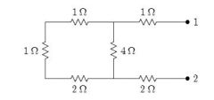
the equivalent resistance between points 1 and 2 of the circuit shown is |
5Ω |
|
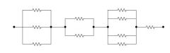
Each of the resistors in the diagram has a resistance of 12Ω. The resistance of the entire circuitis: |
25Ω |
|
|
The resistance of resistor 1 is twice the resistance of resistor 2. The two are connected inparallel and a potential difference is maintained across the combination. Then: |
he current in 1 is half that in 2 |
|
|
The resistance of resistor 1 is twice the resistance of resistor 2. The two are connected in seriesand a potential difference is maintained across the combination. Then: |
the potential difference across 1 is twice that across 2 |
|
|
Resistor 1 has twice the resistance of resistor 2. The two are connected in series and a potentialdifference is maintained across the combination. The rate of thermal energy generation in 1 is: |
twice that in 2 |
|
|
Resistor 1 has twice the resistance of resistor 2. The two are connected in parallel and a po-tential difference is maintained across the combination. The rate of thermal energy generationin 1 is: |
half that in 2 |
|
|
The emf of a battery is equal to its terminal potential difference: |
only when there is no current in the battery |
|
|
The terminal potential difference of a battery is less than its emf: |
only when the battery is being discharged |
|
|
A battery has an emf of 9 V and an internal resistance of 2Ω. If the potential difference acrossits terminals is greater than 9 V |
he current must be out of the negative terminal |
|
|
A battery with an emf of 24 V is connected to a 6-Ωresistor. As a result, current of 3 A existsin the resistor. The terminal potential difference of the battery is |
18 V |
|
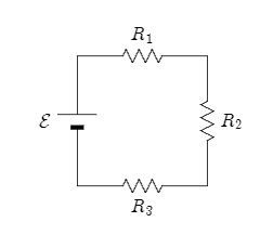
In the diagramR1>R2>R3. Rank the three resistors according to the current in them, leastto greatest. |
all are the same |
|
|
Resistances of 2.0Ω,4.0Ω, and 6.0Ωand a 24-V emf device are all in parallel. The current inthe 2.0-Ωresistor is: |
12A |
|
|
Resistances of 2.0Ω,4.0Ω, and 6.0Ωand a 24-V emf device are all in series. The potentialdifference across the 2.0-Ωresistor is: |
4V |
|
|
A battery with an emf of 12 V and an internal resistance of 1Ωis used to charge a battery withan emf of 10 V and an internal resistance of 1Ω. The current in the circuit is |
1A |
|

In the diagram, the current in the 3-Ωresistor is 4 A. The potential difference between points1 and 2 is: |
20V |
|
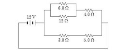
The current in the 5.0-Ωresistor in the circuit shown is |
1.5A |
|
|
A 3-Ωand a 1.5-Ωresistor are wired in parallel and the combination is wired in series to a 4-Ωresistor and a 10-V emf device. The current in the 3-Ωresistor is: |
0.67A |
|
|
A 3-Ωand a 1.5-Ωresistor are wired in parallel and the combination is wired in series to a 4-Ωresistor and a 10-V emf device. The potential difference across the 3-Ωresistor is: |
2V
|
|
|
Two identical batteries, each with an emf of 18 V and an internal resistance of 1Ω, are wired inparallel by connecting their positive terminals together and connecting their negative terminalstogether. The combination is then wired across a 4-Ωresistor. The current in the 4-Ωresistoris: |
4.0A |
|
|
wo identical batteries, each with an emf of 18 V and an internal resistance of 1Ω, are wired inparallel by connecting their positive terminals together and connecting their negative terminalstogether. The combination is then wired across a 4-Ωresistor. The current in each battery is |
2.0A |
|
|
wo identical batteries, each with an emf of 18 V and an internal resistance of 1Ω, are wired inparallel by connecting their positive terminals together and connecting their negative terminalstogether. The combination is then wired across a 4-Ωresistor. The potential difference acrossthe 4-Ωresistor is |
16 V |
|
|
n the diagrams, all light bulbs are identical and all emf devices are identical. In which circuit(A, B, C, D, E) will the bulbs glow with the same brightness as in circuit X? |
|
|
|
In the diagrams, all light bulbs are identical and all emf devices are identical. In which circuit(A, B, C, D, E) will the bulbs be dimmest? |
|
|
|
A 120-V power line is protected by a 15-A fuse. What is the maximum number of “120 V,500 W” light bulbs that can be operated at full brightness from this line? |
3 |
|
|
Two 110-V light bulbs, one “25 W” and the other “100 W”, are connected in series to a 110 Vsource. Then: |
none of the above |
|
|
A resistor with resistanceR1and a resistor with resistanceR2are connected in parallel to anideal battery with emfE. The rate of thermal energy generation in the resistor with resistanceR1is: |
E^2/R1 |
|
|
In an antique automobile, a 6-V battery supplies a total of 48 W to two identical headlights inparallel. The resistance (in ohms) of each bulb is: |
1.5 |
|
|
Resistor 1 has twice the resistance of resistor 2. They are connected in parallel to a battery.The ratio of the thermal energy generation rate in 1 to that in 2 is: |
1 : 2 |
|
|
A series circuit consists of a battery with internal resistancerand an external resistorR.Ifthese two resistances are equal (r=R) then the thermal energy generated per unit time bythe internal resistanceris |
he same as byR |
|
|
The positive terminals of two batteries with emf’s ofE1andE2, respectively, are connectedtogether. HereE2>E1. The circuit is completed by connecting the negative terminals. Ifeach battery has an internal resistancer, the rate with which electrical energy is converted tochemical energy in the smaller battery is |
(E2−E1)E1/2r |
|
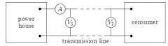
In thefigure, voltmeter V1reads 600 V, voltmeter V2reads 580 V, and ammeter A reads 100 A.The power wasted in the transmission line connecting the power house to the consumer is |
2kW |
|
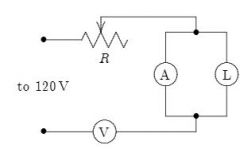
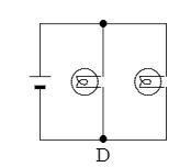
The circuit shown was wired for the purpose of measuring the resistance of the lamp L. Inspec-tion shows that |
he meters, V and A, should be interchanged |
|
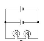
When switch S is open, the ammeter in the circuit shown reads 2.0 A. When S is closed, theammeter reading |
ncreases slightly |
|
|
A certain galvanometer has a resistance of 100Ωand requires 1 mA for full scale deflection. Tomake this into a voltmeter reading 1 V full scale, connect a resistance of: |
900Ωin series |
|
|
To make a galvanometer into an ammeter, connect: |
a low resistance in parallel |
|
|
A certain voltmeter has an internal resistance of 10,000Ωand a range from 0 to 100 V. Togive it a range from 0 to 1000 V, one should connect: |
90,000Ωin series |
|
|
A certain ammeter has an internal resistance of 1Ωand a range from 0 to 50 mA. To make itsrange from 0 to 5 A, use: |
a resistance of 1/99Ωin parallel |
|
|
A galvanometer has an internal resistance of 12Ωand requires 0.01 A for full scale deflection.To convert it to a voltmeter reading 3 V full scale, one must use a series resistance of: |
288Ω |
|
|
A certain voltmeter has an internal resistance of 10,000Ωand a range from 0 to 12 V. Toextend its range to 120 V, use a series resistance of: |
90,000Ω |
|
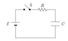
Four circuits have the form shown in the diagram. The capacitor is initially uncharged and theswitch S is open. SThe values of the emfE, resistanceR, and capacitanceCfor each of the circuits arecircuit 1:E=18V,R=3Ω,C=1μFcircuit 2:E=18V,R=6Ω,C=9μFcircuit 3:E=12V,R=1Ω,C=7μFcircuit 4:E=10V,R=5Ω,C=7μFRank the circuits according to the current just after switch S is closed least to greatest. |
4, 2, 1, 3 |
|

Four circuits have the form shown in the diagram. The capacitor is initially uncharged and theswitch S is open The values of the emfE, resistanceR, and capacitanceCfor each of the circuits arecircuit 1:E=18V,R=3Ω,C=1μFcircuit 2:E=18V,R=6Ω,C=9μFcircuit 3:E=12V,R=1Ω,C=7μFcircuit 4:E=10V,R=5Ω,C=7μFRank the circuits according to the time after switch S is closed for the capacitors to reach halftheirfinal charges, least to greatest |
1, 3, 4, 2 |
|
|
The time constantRChas units of |
none of these |
|
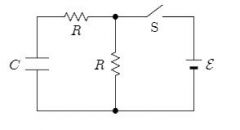
n the circuit shown, both resistors have the same valueR. Suppose switch S is initially closed.When it is then opened, the circuit has a time constantτa. Conversely, suppose S is initiallyopen. When it is then closed, the circuit has a time constant τb. The ratioτa/τbis |
2 |
|
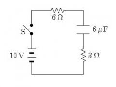
In the circuit shown, the capacitor is initially uncharged. At timet= 0, switch S is closed. Ifτdenotes the time constant, the approximate current through the 3Ωresistor whent=τ/10is: |
1A |
|
|
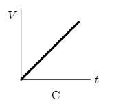
Suppose the current charging a capacitor is kept constant. Which graph below correctly givesthe potential differenceVacross the capacitor as a function of time? |
|
|
|
A charged capacitor is being discharged through a resistor. At the end of one time constantthe charge has been reduced by (1−1/e) = 63% of its initial value. At the end of two timeconstants the charge has been reduced by what percent of its initial value? |
86% |
|
|
An initially uncharged capacitor C is connected in series with resistor R. This combination isthen connected to a battery of emfV0.Sufficient time elapses so that a steady state is reached.Which of the following statements is NOT true? |
The total thermal energy generated by R is independent ofR |
|
|
A certain capacitor, in series with a resistor, is being charged. At the end of 10 ms its chargeis half thefinal value. The time constant for the process is about: |
14ms |
|
|
A certain capacitor, in series with a 720-Ωresistor, is being charged. At the end of 10 ms itscharge is half thefinal value. The capacitance is about: |
20μF |
|
|
In the capacitor discharge formulaq=q0e−t/RCthe symboltrepresents: |
none of the above |
|
|
Units of a magneticfield might be |
kg/C·s |
|
|
In the formulanF=qv×B |
Fmust be perpendicular to bothvandB |
|
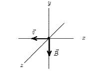
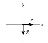
An electron moves in the negativexdirection, through a uniform magneticfield in the negativeydirection. The magnetic force on the electron is |
in the negative z direction |
|
|
At any point the magneticfield lines are in the direction of |
none of the above |
|
|
The magnetic force on a charged particle is in the direction of its velocity if |
never |
|
|
A magneticfield exerts a force on a charged particle |
if the particle is moving across thefield line |
|
|
The direction of the magneticfield in a certain region of space is determined byfiring a testcharge into the region with its velocity in various directions in different trials. Thefield directionis: |
one of the directions of the velocity when the magnetic force is zero |
|
|
An electron is moving north in a region where the magneticfield is south. The magnetic forceexerted on the electron is: |
zero |
|
|
A magneticfield CANNOT: |
change the kinetic energy of a charged particle |
|
|
A proton (chargee), traveling perpendicular to a magneticfield, experiences the same force asan alpha particle (charge 2e) which is also traveling perpendicular to the samefield. The ratioof their speeds,vproton/valpha, is |
2 |
|
|
A hydrogen atom that has lost its electron is moving east in a region where the magneticfieldis directed from south to north. It will be deflected |
up |
|
|
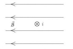
A beam of electrons is sent horizontally down the axis of a tube to strike afluorescent screenat the end of the tube. On the way, the electrons encounter a magneticfield directed verticallydownward. The spot on the screen will therefore be deflected: |
to the right as seen from the electron source |
|
|
An electron (charge =−1.6×10⁻¹⁹C) is moving at 3×10⁵m/s in the positivexdirection. Amagneticfield of 0.8 T is in the positivezdirection. The magnetic force on the electron is |
4×10⁻¹⁴N, in the positiveydirection |
|
|
At one instant an electron (charge =−1.6×10⁻¹⁹C) is moving in thexyplane, the componentsof its velocity beingvx=5×10⁵m/s andvy=3×10⁵m/s. A magneticfield of 0.8 T is in thepositivexdirection. At that instant the magnitude of the magnetic force on the electron is |
3.8×10⁻¹⁴N |
|
|
At one instant an electron (charge =−1.6×10⁻¹⁹C) is moving in thexyplane, the componentsof its velocity beingvx=5×10⁵m/s andvy=3×10⁵m/s. A magneticfield of 0.8 T is in thepositivexdirection. At that instant the magnitude of the magnetic force on the electron is |
3.8×10⁻¹⁴N |
|
|
An electron travels due north through a vacuum in a region of uniform magneticfieldnBthatis also directed due north. It will |
be unaffected by thefield |
|
|
At one instant an electron is moving in the positivexdirection along thexaxis in a regionwhere there is a uniform magneticfield in the positivezdirection. When viewed from a pointon the positivezaxis, it subsequent motion is |
counterclockwise around a circle in thexyplane |
|
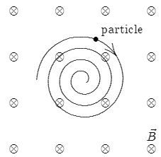
A uniform magneticfield is directed into the page. A charged particle, moving in the plane ofthe page, follows a clockwise spiral of decreasing radius as shown. A reasonable explanation is: |
he charge is negative and slowing down |
|
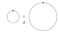
An electron and a proton each travel with equal speeds around circular orbits in the sameuniform magneticfield, as shown in the diagram (not to scale). Thefield is into the page onthe diagram. Because the electron is less massive than the proton and because the electron isnegatively charged and the proton is positively charged: |
he electron travels clockwise around the smaller circle and the proton travels counter-clockwise around the larger circle |
|
|
An electron is launched with velocitynvin a uniform magneticfieldnB. The angleθbetweennvandnBis between 0 and 90◦. As a result, the electron follows a helix, its velocity vectornvreturning to its initial value in a time interval of: |
2πm/eB |
|
|
An electron and a proton are both initially moving with the same speed and in the samedirection at 90◦to the same uniform magneticfield. They experience magnetic forces, whichare initially |
equal in magnitude but opposite in direction |
|
|
An electron enters a region of uniform perpendicularnEandnBfields. It is observed that thevelocitynvof the electron is unaffected. A possible explanation is |
nvis perpendicular to bothnEandnBand has magnitudeE/B |
|
|
A charged particle is projected into a region of uniform, parallel,nEandnBfields. The force onthe particle is |
at some angle<90◦with thefield lines |
|
|
A uniform magneticfield is in the positivezdirection. A positively charged particle is movingin the positivexdirection through thefield. The net force on the particle can be made zeroby applying an electricfield in what direction? |
Negativey |
|
An electron is traveling in the positivexdirection. A uniform electricfieldnEis in the negativeydirection. If a uniform magneticfield with the appropriate magnitude and direction alsoexists in the region, the total force on the electron will be zero. The appropriate direction forthe magneticfield is |
nto the page |
|
|
An ion with a charge of +3.2×10⁻¹⁹C is in a region where a uniform electricfield of 5×10⁴V/mis perpendicular to a uniform magneticfield of 0.8 T. If its acceleration is zero then its speedmust be: |
6.3×10⁴m/s |
|
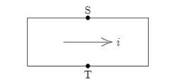
The current is from left to right in the conductor shown. The magneticfield is into the pageand point S is at a higher potential than point T. The charge carriers are: |
positive |
|
|
Electrons (massm, charge−e) are accelerated from rest through a potential differenceVandare then deflected by a magneticfieldnBthat is perpendicular to their velocity. The radius ofthe resulting electron trajectory is: |
sqrt(2mV /e)/B |
|
|
In a certain mass spectrometer, an ion beam passes through a velocityfilter consisting ofmutually perpendicularfieldsnEandnB. The beam then enters a region of another magneticfieldnBIperpendicular to the beam. The radius of curvature of the resulting ion beam isproportional to: |
E/BB' |
|
|
A cyclotron operates with a given magneticfield and at a given frequency. IfRdenotes theradius of thefinal orbit, thefinal particle energy is proportional to: |
R^2 |
|
|
J. J. Thomson’s experiment, involving the motion of an electron beam in mutually perpendic-ularnEandnBfields, gave the value of: |
charge/mass ratio for electrons |
|

The diagram shows a straight wire carrying aflow of electrons into the page. The wire isbetween the poles of a permanent magnet. The direction of the magnetic force exerted on thewire is: |
↑ |
|
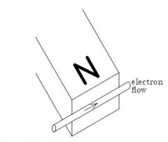
Thefigure shows the motion of electrons in a wire that is near the N pole of a magnet. Thewire will be pushed |
upwards |
|
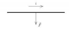
The diagram shows a straight wire carrying currentiin a uniform magneticfield. The magneticforce on the wire is indicated by an arrow but the magneticfield is not shown. Of the followingpossibilities, the direction of the magneticfield is |
out of the page |
|
Thefigure shows a uniform magneticfieldnBdirected to the left and a wire carrying a currentinto the page. The magnetic force acting on the wire is |
toward the top of the page |
|
|
A loop of wire carrying a current of 2.0 A is in the shape of a right triangle with two equal sides,each 15 cm long. A 0.7 T uniform magneticfield is parallel to the hypotenuse. The resultantmagnetic force on the two equal sides has a magnitude of |
0 |
|
|
A loop of wire carrying a current of 2.0 A is in the shape of a right triangle with two equalsides, each 15 cm long. A 0.7 T uniform magneticfield is in the plane of the triangle and isperpendicular to the hypotenuse. The magnetic force on either of the two equal sides has amagnitude of: |
0.15 N |
|
|
A current is clockwise around the outside edge of this page and a uniform magneticfield isdirected parallel to the page, from left to right. If the magnetic force is the only force actingon the page, the page will turn so the right edge: |
moves toward you |
|
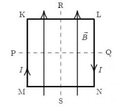
A square loop of wire lies in the plane of the page and carries a current I as shown. There is auniform magneticfieldnBparallel to the side MK as indicated. The loop will tend to rotate |
about PQ with KL coming out of the page |
|
|
The units of magnetic dipole moment are |
ampere·meter^2 |
|
|
You are facing a loop of wire which carries a clockwise current of 3.0 A and which surroundsan area of 5.8×10⁻²m2. The magnetic dipole moment of the loop is |
0.17 A·m2, awayfrom you |
|
|
The magnetic torque exerted on aflat current-carrying loop of wire by a uniform magneticfieldnBis: |
maximum when the plane of the loop is parallel tonB |
|
|
A circular loop of wire with a radius of 20 cm lies in thexyplane and carries a current of 2 A,counterclockwise when viewed from a point on the positivezaxis. Its magnetic dipole momentis: |
0.25 A·m2, in the positivezdirection |
|
|
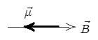
The diagrams showfive possible orientations of a magnetic dipolenμin a uniform magneticfieldnB. For which of these does the magnetic torque on the dipole have the greatest magnitude? |
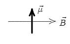
|
|
|
The magnetic dipole moment of a current-carrying loop of wire is in the positivezdirection.If a uniform magneticfield is in the positivexdirection the magnetic torque on the loop is: |
in the positiveydirection |
|
|
For a loop of current-carrying wire in a uniform magneticfield the potential energy is a minimumif the magnetic dipole moment of the loop is |
i the same direction as thefield |
|
|
The diagrams showfive possible orientations of a magnetic dipolenμin a uniform magneticfieldnB. For which of these is the potential energy the greatest?
|
|
|
|
A loop of current-carrying wire has a magnetic dipole moment of 5×10⁻⁴A·m2. The momentinitially is aligned with a 0.5-T magneticfield. To rotate the loop so its dipole moment isperpendicular to thefield and hold it in that orientation, you must do work of |
2.5×10⁻⁴J |